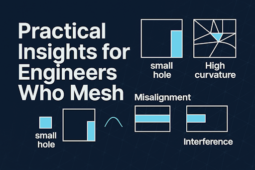
Why Geometry Is Challenging in CAE: A Practical Guide
Geometry quietly shapes every stage of CAE. Before considering solvers, materials, or boundary conditions, geometry sets the boundaries of what’s achievable. It determines whether meshing will be straightforward or exasperating, if analysis is dependable or vulnerable, and whether engineers are problem-solving or grappling with CAD. Despite its vital role, geometry is often overlooked as a solved issue—but it remains a persistent bottleneck in simulation workflows. Recognizing this is the first step to overcoming it. This article provides a practical, accessible look at why geometry poses challenges in CAE—focusing on everyday model preparation for meshing and analysis.
CAD Geometry Isn't Created for CAE
Most CAE difficulties originate from one fact: CAD models are made for manufacturing, not simulation.
Manufacturing-centric CAD includes:
- Precise mathematical surfaces (NURBS, analytic primitives)
- Small fillets, chamfers, and decorative details
- Exact tolerances essential for machining, but not physics
- Complex histories and parametric relationships
CAE requires distinct qualities:
- Sealed, orderly topology
- Simplified features
- Reliable surface intersections
- Uniform normals and orientations
- Absence of sliver faces, gaps, or micro-edges
This disparity is at the heart of most geometry cleanup tasks.
Real-World Geometry Is Imperfect
Even meticulously crafted CAD models accumulate flaws:
Typical problems include:
- Gaps where surfaces should connect
- Overlaps due to misaligned intersections
- Sliver faces with extreme aspect ratios
- Tiny edges that hinder mesh generation
- Irregular topology from repeated exports or conversions
- Non-manifold edges introduced by Boolean operations
These flaws may escape notice in CAD but can severely disrupt meshing. Mesh generators demand clean, consistent, watertight boundaries—anything less causes failures or produces meshes prone to collapse.
Geometry Tolerances Are Tricky
Each CAD system uses its own internal tolerances—often undisclosed and always inconsistent.
Resulting issues include:
- A “closed” edge in CAD turns into a gap in CAE.
- A face “nearly planar” in CAD proves insufficient for meshing.
- Minor features overlooked in CAD become major constraints in the mesh.
CAE tools must determine if close points should merge—a risky judgment. Merge too much and key features vanish; merge too little and gaps break the mesh.
Boolean Operations Can Be Unreliable
Boolean operations (union, subtract, intersect) drive geometry setup. Yet they're among the most failure-prone steps.
Why Booleans falter:
- Intersections between curved surfaces demand complex mathematics
- Minuscule features complicate intersection curves
- Tolerances accumulate with each operation
- CAD kernels interpret topology differently
When Booleans fail, models may appear visually intact but are topologically invalid. This leads to meshing failures or poor-quality meshes that compromise analysis accuracy.
Simplifying Geometry Is Essential but Risky
CAE engineers regularly remove features like:
- Small holes
- Fillets
- Ribs
- Logos
- Decorative elements
Yet simplification isn't simple. Removing features may:
- Introduce new sliver faces
- Disrupt adjacent topology
- Cause self-intersections
- Alter physical behavior if done incorrectly
Effective simplification means identifying what impacts physics—and using tools that preserve model integrity.
Assemblies Amplify the Challenges
Single parts pose their own problems; assemblies intensify them.
Assemblies bring:
- Misaligned mating surfaces
- Interference fits
- Overlapping solids
- Missing fasteners
- Inconsistent coordinate systems
- Mixed units or tolerances
- Contact definitions tied to geometry
CAE workflows often require:
- Defeaturing
- Merging
- Imprinting
- Creating shared topology
- Identifying contact pairs
Each step depends heavily on geometry quality.
Meshing Displays Every Imperfection
Meshing exposes geometry weaknesses.
Issues for meshing include:
- Acute angles
- Tiny edges
- Highly curved regions
- Non-manifold edges
- Degenerate surfaces
- Poorly trimmed NURBS patches
Mesh generators must strictly adhere to geometry—even when it's flawed. That's why engineers often say: “The mesh reveals the truth about your geometry.”
Geometry Repair Tools Help, But Have Limits
Modern CAE platforms offer:
- Auto-repair
- Healing
- Stitching
- Gap closure
- Feature removal
- Surface reconstruction
These tools are vital, yet imperfect. Guided by heuristics and tolerances, they can:
- Overheal, merging things that shouldn't combine
- Underheal, leaving gaps that still break meshes
- Create new artifacts while resolving old ones
Human oversight remains essential in geometry repair.
The Core Challenge: Geometry Is a Graph
Beneath the surface, geometry consists of a topological graph:
- Nodes (vertices)
- Edges
- Faces
- Shells
- Solids
When this structure becomes inconsistent, everything downstream suffers. Engineers often fix geometry without realizing they're restoring a graph—grasping this concept is crucial for improving tools and achieving robust geometry.
Conclusion: Geometry's Difficulty Lies in Its Foundations
Geometry complicates CAE because:
- CAD and CAE serve different purposes
- Real-world models have imperfections
- Tolerances aren't uniform
- Booleans are delicate
- Simplification brings risk
- Assemblies add complexity
- Meshing highlights every defect
- Repair tools can't solve everything
- Topology is fundamentally fragile
Still, these challenges create opportunities. Enhanced tools, smarter workflows, and greater understanding can free up engineers from geometry struggles, allowing more focus on true engineering.
making geometry and meshing clear, practical, and accessible.